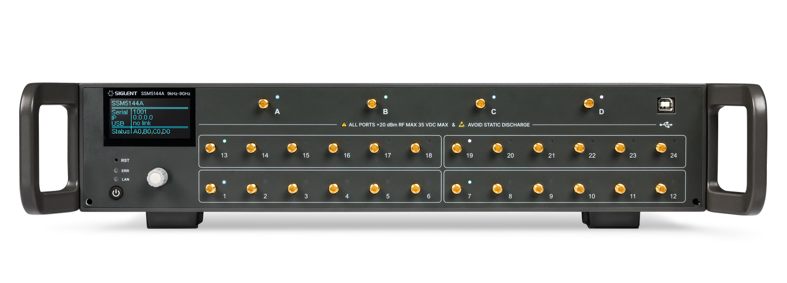
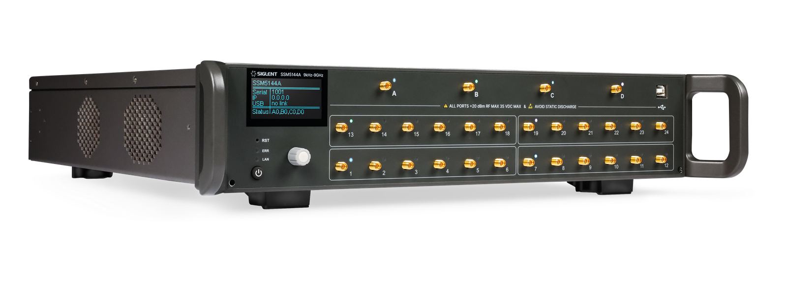
SSM5000A — RF Switch Matrix, up to 26.5 GHz
RF switch matrix for expanding the test ports of vector network analyzers, signal sources and spectrum analyzers. The SSM5000A family supports up to 4 input ports and up to 24 output ports, with LAN, USB Device and Direct Control interfaces for automated multi-port RF test systems.
| Model | Frequency Range | Inputs | Outputs | Max Input DC | Max Input Power |
|---|---|---|---|---|---|
| SSM5122A | 9 kHz – 9 GHz | 2 | 12 | 35 V | 20 dBm |
| SSM5124A | 9 kHz – 9 GHz | 2 | 24 | 35 V | 20 dBm |
| SSM5142A | 9 kHz – 9 GHz | 4 | 12 | 35 V | 20 dBm |
| SSM5144A | 9 kHz – 9 GHz | 4 | 24 | 35 V | 20 dBm |
| SSM5321A | 100 kHz – 26.5 GHz | 2 | 6 | 35 V | 20 dBm |
| SSM5342A | 100 kHz – 26.5 GHz | 4 | 12 | 35 V | 20 dBm |
Key Features
Expand VNA, Signal Source and Spectrum Analyzer Ports
Use one switch matrix to extend limited instrument ports across multiple DUTs. It is suitable for network analyzer S-parameter testing, signal-generator routing, spectrum-analyzer receive-path testing and multi-port RF production fixtures.
Up to 4 Inputs and 24 Outputs
The family supports configurations from 2×6 to 4×24. This avoids buying several instruments just to reach more RF ports and reduces manual cable reconnection during repetitive test sequences.
9 GHz and 26.5 GHz Model Families
Choose 9 GHz models for sub-6 GHz, Wi-Fi, 5G FR1 and general RF work. Choose 26.5 GHz models for microwave applications, K-band components and higher-frequency RF module test benches.
Simplified Multi-port Calibration Workflow
The switch matrix supports a simplified multi-port calibration algorithm. This improves calibration efficiency when testing multiple DUTs or many S-parameter paths through a VNA-based setup.
LAN, USB Device and Direct Control
LAN and USB Device support PC-controlled automated test. Direct Control input and output allow switch-matrix expansion and coordinated switching with compatible instruments or larger RF switching setups.
19-inch Rack-oriented RF Test Integration
The chassis is suitable for 19-inch rack systems and automated RF benches. Typical use cases include antenna test, 5G component-module test, RF frontend validation and production screening.
Specifications
| Parameter | Unit | Value / Description |
|---|---|---|
| RF SWITCH MATRIX | ||
| Maximum frequency | GHz | 9 or 26.5, model-dependent |
| Frequency range | — | 9 kHz–9 GHz models · 100 kHz–26.5 GHz models |
| Maximum input ports | — | 4 |
| Maximum output ports | — | 24 |
| RF connector | — | 3.5 mm female |
| Characteristic impedance | Ω | 50 |
| Maximum input power | dBm | 20 |
| Maximum input DC voltage | V | 35 |
| CONTROL AND INTEGRATION | ||
| Interfaces | — | LAN · USB Device · Direct Control in · Direct Control out |
| Calibration support | — | Simplified multi-port calibration algorithm |
| Display | inch | 2.4 |
| Chassis size | mm | 88.5 × 425 × 417.6 |
Applications
Multi-port S-parameter Testing
Expand a vector network analyzer into 24 single ports, 12 full 2-port paths, 8 full 3-port paths, 6 full 4-port paths or other multi-port configurations depending on fixture requirements.
Multi-DUT RF Module Screening
Automate routing between multiple RF DUTs in production. This reduces manual cable handling, improves repeatability and shortens test time for RF frontend modules and communication boards.
Generator-to-Multiple-Port Distribution
Route one signal source to many DUT inputs during receiver or module test. The matrix reduces the number of RF sources required in a multi-port validation bench.
Multi-port Receive Measurement
Switch multiple DUT outputs into one spectrum analyzer for emission, power, harmonic or receiver-path checks without repeated cable reconnection.
Antenna and Array Measurement
Use the matrix for antenna, array and multi-port RF structures where many feed points need systematic VNA or spectrum-analyzer measurement.
5G RF Component Module Test
Suitable for sub-6 GHz and microwave RF module benches where many RF paths must be tested with controlled switching and repeatable calibration.
Similar Products